Share This Page
| Home | | Mathematics | | * Applied Mathematics | | * Storage Tank Modeling | | | | Share This Page |
Analyzing and modeling a real-world tank with an odd shape
Copyright © 2013, Paul Lutus — Message Page
This article describes a typical storage tank analysis case history, using the methods I created with TankProfiler, which has been written to go beyond what my earlier program TankCalc can meaningfully analyze.
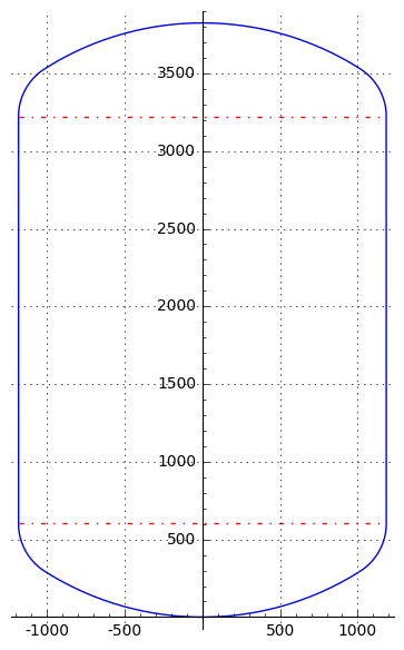
A few months ago I received an inquiry from a TankCalc user who needed to analyze a rather oddly-shaped tank, one that I quickly realized TankCalc wouldn't be able to model very accurately. The tank's overall profile is shown in Figure 1 above. The tank's end caps aren't elliptical, nor are they spherical, nor, for that matter, do they have any other classic geometric shape.
During the exchange about this tank's shape, my correspondent revealed that the end caps consist of two separate sections with different radii, welded together. One radius is evident at the bend between the main end cap and the cylindrical section, the other radius is evident at the center of the end cap. I realized if I wanted to accurately analyze this tank, I would need to write a new analysis method, one that relied on an incremental profile rather than by choosing from the handful of classic geometries offered by TankCalc (that new method became TankProfiler). Then I would need to write a routine that used the tank's description to create a profile suitable for TankProfiler.
My correspondent provided a drawing of his tank and this description: "The end cap is not so straightforward to describe mathematically. The section of the end cap is composed of two circle sectors with different radii. The radius of each circular sector is calculated based on the tank's diameter. So we have the radius of the top circular sector R=0.8*D, and the small circular sector that unites the top with the cilinder [sic] (the rounded corner actually) has R=(1/6.5)*D" [D = tank diameter]. He went on to say that this two-radius arrangement is common in cryogenic storage tank fabrication, with differences in the specified dimensions for different purposes.
A small digression. As I began this correspondence, it occurred to me that there are many tanks in the field that don't have simple geometric shapes, so one of my assumptions about TankCalc (which requires tanks to have such shapes) was at least partly wrong. But given the existence of computers and powerful mathematical analysis tools, why should tank fabricators struggle to make their tanks agree with simple preconceptions about their shape? This cryogenic tank was obviously the logical outcome of an efficient manufacturing process, and it has a rather odd shape, but not one that's particularly difficult to analyze. This tank needs to be analyzed using a stepwise dimensional profile, not a pure mathematical model like that used in TankCalc, but a dimensional profile is relatively easy to create. My thinking now is that mathematical tank analysis should agree with efficient manufacturing methods, not force tank fabricators to use a shape that might cause the tank's cost to increase — in the modern era, mathematics is almost always cheaper than welding metal in a particular way.
After some preliminary work using Sage (my current favorite tool for mathematical analysis), I realized I could produce a very accurate profile of the tank based only on the provided information. Here's a diagram of my analysis generated in Sage:
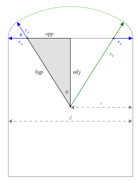
For simplicity, Figure 2 shows one of two end caps. All the relevant variable names appear in Figure 2. Here are their definitions:
- d = tank diameter.
- r = tank radius = $\frac{d}{2}$.
- ra = the smaller of the two end cap radii, that defining the "corner" between the cylindrical section and the main end cap section (blue in Figure 2).
- rb = the larger of the two end cap radii, that defining the center of the end cap (green in Figure 2).
- adj, opp, hyp = three sides of the gray right triangle that's key to analyzing this tank.
- φ = the angle between hyp and adj, also the angle between the tank's vertical centerline and the junction between the large and small radii, as seen from the triangle's lower extent.
- θ = the angle between hyp and opp, also the angle subtending the extent of the small radius.
Here are notes on the analysis and the equations that resulted:
- As a preliminary step toward generating a dimensional profile, I saw that I needed to use the available information — the tank's overall dimensions and the two provided end cap radii — to create an accurate diagram of the tank.
- After some thought I realized that an analysis based on a right triangle could be used to compute the unknowns.
- Because of its location at the transition between the end cap and the cylindrical wall, I saw that the length of the triangle's opposite side (opp in Figure 2) was equal to the tank's radius minus ra:
(1) $opp = r-r_a$.
- In the same way, the length of the triangle's hypotenuse (hyp in Figure 2) was equal to the greater radius minus the smaller radius:
(2) $hyp = r_b - r_a$
- With opp and hyp defined, I can compute adj, the triangle's third side:
(3) $adj = \sqrt{hyp^2 - opp^2}$
- Now that we have three triangle sides, I can compute the two required angles φ and θ:
- (4) $\phi = \tan^{-1}(\frac{opp}{adj})$
- (5) $\theta = \tan^{-1}(\frac{adj}{opp})$ or $\frac{\pi}{2} - \phi$
With all the required quantities computed as described above, one can then generate a dimensional profile that consists of end caps having the two differing radii, and the cylinder wall. Any suitable method can be used to generate a profile, I favor Python simply because it produces useful results very quickly. Here is a link to the Python script I used to create this tank's profile.
The generated profile is then submitted to TankProfiler, which will produce a table that correlates tank sensor height and partial content volume or the reverse, as well as additional information about the tank — its total volume, surface area and (if a wall thickness is provided) the volume of the tank itself. TankProfiler will also create a diagram like that shown in Figure 1.
It's important to say that this method isn't limited to the dimensions specified for this example tank — most dimensions will be accepted, with certain constraints:
- rb must be larger than r.
- ra must be smaller than rb
Tanks like this, and others like it, are quite common, more common than I realized when I wrote TankCalc. As it turns out, TankCalc makes some simplifying assumptions about tank shapes that I'm discovering aren't realistic. The advantage of TankProfiler, coupled with an analysis like that above, is that it produces very accurate results for tanks that don't have easily defined shapes. The drawback is that TankProfiler's users need to know more than those who use TankCalc — they need to be comfortable running Python programs at the command line (no fancy user interface) and for a tank not analyzed by others, they should be able to perform a mathematical analysis like that above.Obviously one can get reasonably accurate results from TankCalc for a tank like this that doesn't have a classical geometric shape. When this tank is submitted to TankCalc with the assumption that the end caps are elliptical, the volume errors are less than 10% for all but the very smallest partial volumes (i.e. when the tank is nearly empty). This method is intended for those who need the highest practical accuracy. If provided with a carefully analyzed, well-written profile as in the above example, TankProfiler produces very accurate results and accommodates the many tank shapes outside those that can be managed by TankCalc.
| Home | | Mathematics | | * Applied Mathematics | | * Storage Tank Modeling | | | | Share This Page |